Geotechnical Failures
(1) It is a part of the normal "standard of care" to determine soil conditions before designing and constructing a foundation or pavement system.
(2) The Texas Section of the American Society of Civil Engineers (ASCE) "Recommended Practice for the Design of Residential Foundations" requires that "prior to foundation design, a geotechnical investigation and report shall be completed by a Geotechnical Engineer."
(3) The International Building Code (IBC) Section 1803 requires a soil investigation be performed for the design of new foundation elements except where waived by the "building official" if satisfactory subsurface information from adjacent areas is available. Be careful on how you define "satisfactory". The IBC also states "in areas likely to have expansive soil, the building official shall require soil tests to determine where such soils do exist." Many areas in Central Texas are likely to have expansive clay soil, therefore a geotechnical study is be default required.
(4) Structural home warranty companies such as 2-10 HBW require a geotechnical evaluation for every house lot. If a Builder does not have a geotechnical evaluation performed, they set themselves up for a conflict with the warranty company with regards to whom might have to pay for repairs.
If you are an Owner, Developer, Contractor, Subcontractor, or Architect, please realize the permanent burden of responsibility put on engineers before considering their work "too conservative" or as we prefer to say "safe". "Safe" and "engineering" are supposed to be synonymous. The alternative is just plain reckless. Unfortunately, with limited budgets, engineers already work at the margin of safe and risky, particularly on residential and small commercial projects.

This is another image of the San Antonio wall failure.
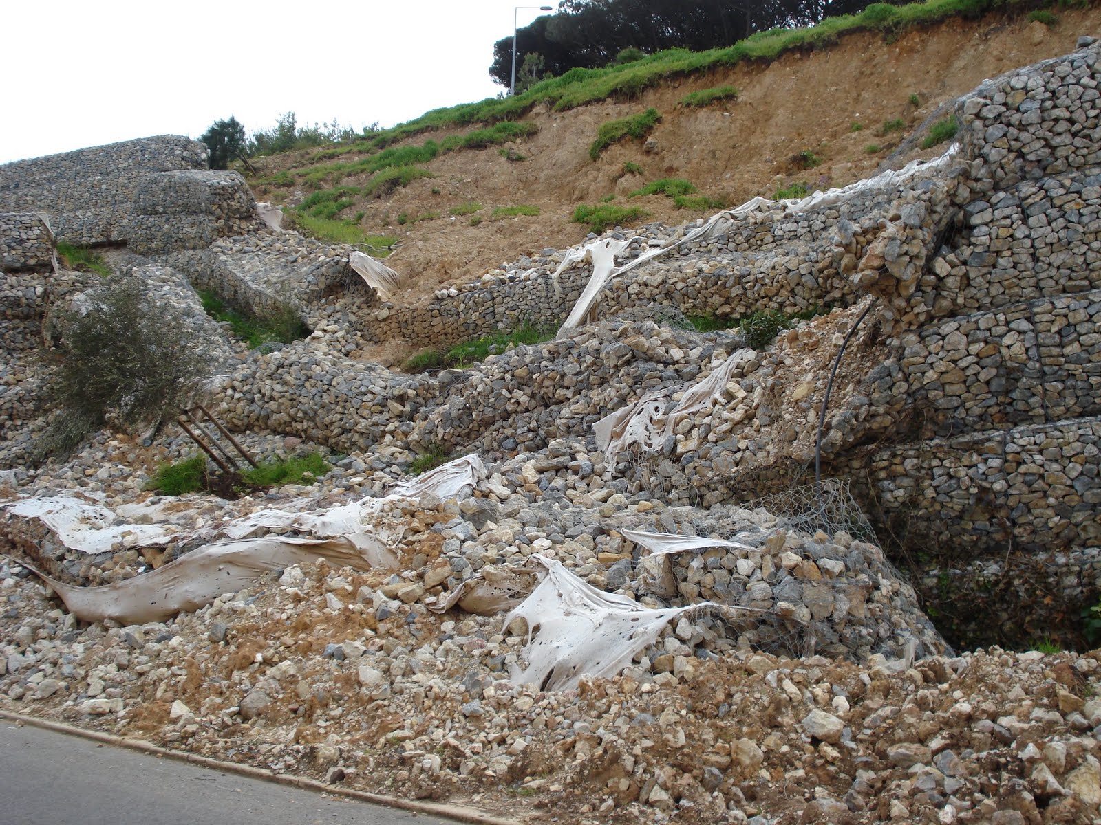
This is an example of a gabion wall failure.
RETAINING WALL FAILURES
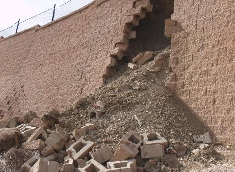
Another retaining wall failure. Appears to be a local stability failure of a segmental block retaining wall (or improper reinforcement detailing or installation), therefore this is more of a structural failure than a geotechnical type failure.
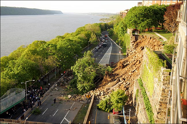
A retaining wall failure instigated a landslide that covered this busy street in New York City area. The 75-ft tall wall collapsed in 2 events.
This was an MSE wall failure apparently caused by expansive clay backfill or native cut face behind the backfill zone exerting earth pressure exceeding value used in design. Photo by Paul Spraggins of TxDOT.
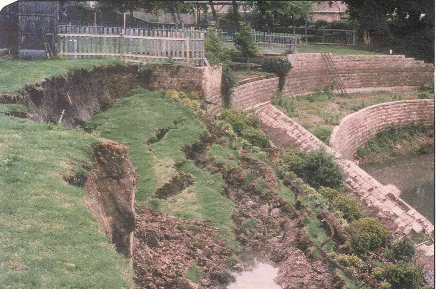
Here is a terraced retaining wall system that failed, most likely due to a lack of an engineered design.
In May 2014, Baltimore, Maryland, an apparent mortared stone block retaining wall (gravity wall?) failed after heavy rain, causing pavement and parked cars to fall and debris covered the nearby railroad track. There is a video of the collapse from a witness standing in front of the townhouses (find it on youtube).
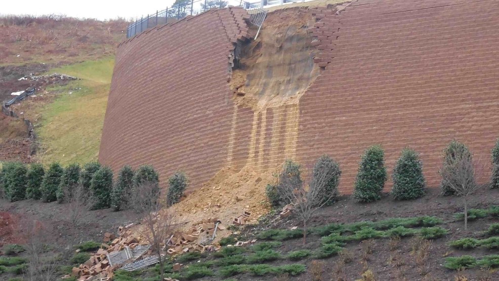
This segmental block retaining wall in Roanoke, Virginia, experienced a partial failure, likely related to saturation of the backfill (poor drainage). The designs and construction QC of notably tall retaining walls should be checked and double-checked.
SETTLEMENT FAILURES:
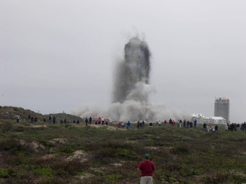
This is a picture of a high rise building being demolished in South Padre due to poor geotechnical design that led to ridiculous amounts of settlement. Read about it more here:
South Padre Building Settlement
Lakeport, California, 2013. Approximately 20 homes are abandoned after fissures and settlement of up to 10 feet destroy homes and make subdivision worthless. Quick but progressive settlement from March to May. I
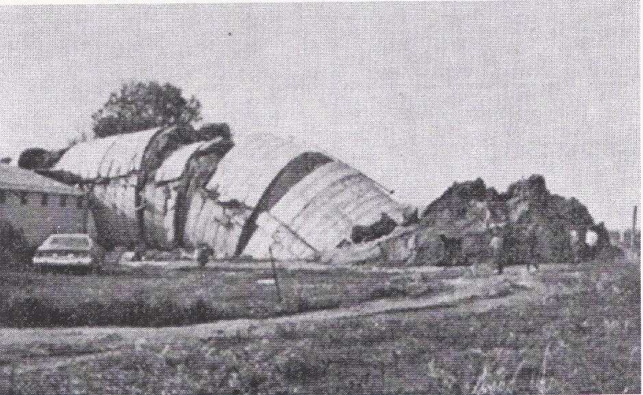
Bearing capacity failures are rare but do occur. This is a photo of an infamous grain silo collapse that every geotechnical engineering student learns about when studying basic bearing capacity equations.
EXCAVATION BRACING FAILURES:
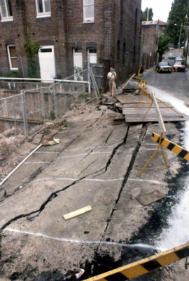
This is a distressed street area adjacent to a failed pier wall bracing system (to left). Urban excavations require rigid bracing to limit or prevent movement behind the wall. This system obviously was not properly designed or constructed.
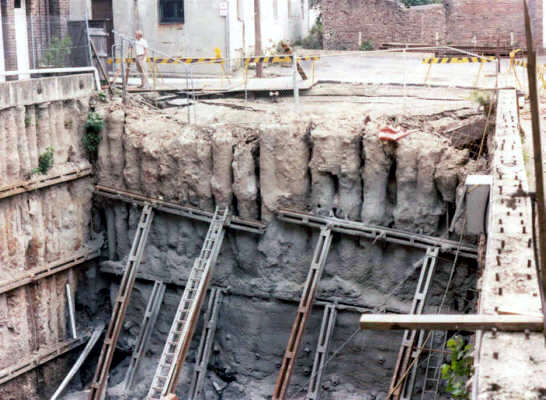
Here is a photograph of that pier wall, with new bracing installed to prevent further movement.
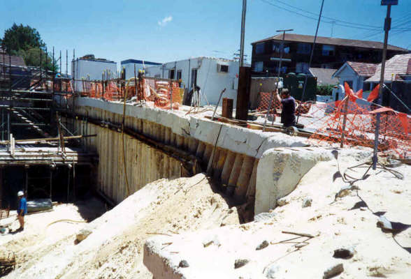
Here is another pier wall that deflected excessively (failed) at the lower elevations and required a quickly constructed soil berm to prevent further movement.
Here is an image of a failed soldier-pile and wood lagging excavation bracing system in 1984. Global instability failure due to system embedment being too shallow is the likely cause. Note vertical scarp face in front of street and behind wall.
ROCKFALLS and ROCK SLOPE or BLUFF STABILITY:
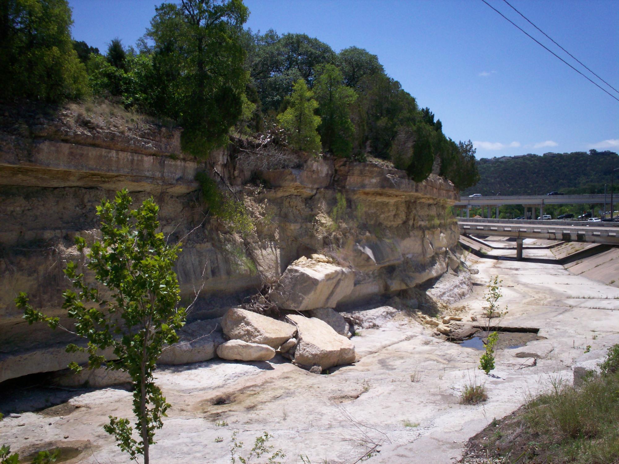
Vertical or near-vertical cut faces in limestone rock materials are not stable over the long term. Wedge-type failures, planar-type failures, and shallow sloughing failures will periodically occur as seen in this photo as the exposed surface is subject to weathering processes.
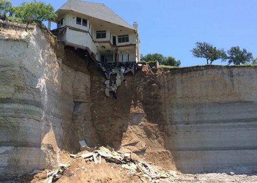
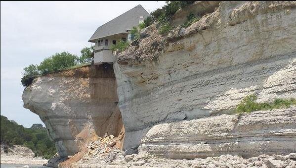
A limestone bluff failure occurred in Lake Whitney in Texas in 2014. The exterior covered patio collapsed with the failed rock mass and the house had to be abandoned and demolished by burning. Photo credit: WFAA-TV.
Here is another view of the Lake Whitney failure. Appears to have been a large wedge-type failure. Do not construct homes near bluffs, particularly without a geotechnical engineering site evaluation. Photo credit: WFAA-TV, Dallas, Texas.
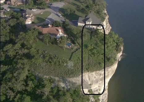
Another view of the Lake Whitney site. Note the fracture (fissure) exposed at the surface of the rock mass. The bluff is not vertical but worse is recessed underneath the top (concave inward). The rock mass in front of the house in this photograph is close to imminent failure and will collapse as well. Photo credit: WFAA-TV
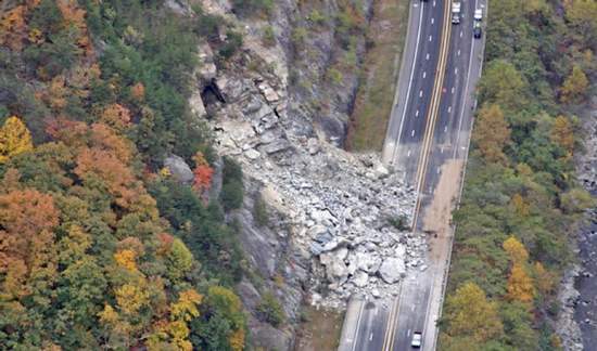
This is a wedge-type rock slide that occurred in North Carolina.
This is a large toppling failure of sedimentary rock in Normandy, France, that was caught on video by a bystander in 2013. Luckily no one was on the beach downslope of the rock bluff. Do not build grade-supported structures at the top of a bluff unless you accept the risks.
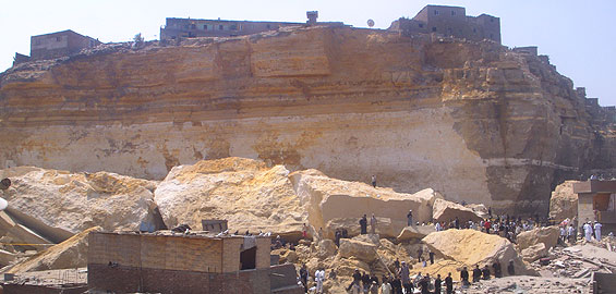

In 2008 a large apparent rock toppling failure occurred in Cairo, Egypt, tragically killing over 100 people in the developed area below the vertical rock face. Local geologists had already predicted the hazard:
http://engineering.kau.edu.sa/Files/135Researches/59067_29414.pdf
Rockfall hazards exist anywhere there is a vertical or steep slope face in rock materials without any man-made protection. Buffers or other mitigation measures are required when constructing roads, parking lots, or structures near the base of steep cuts in rock geology.
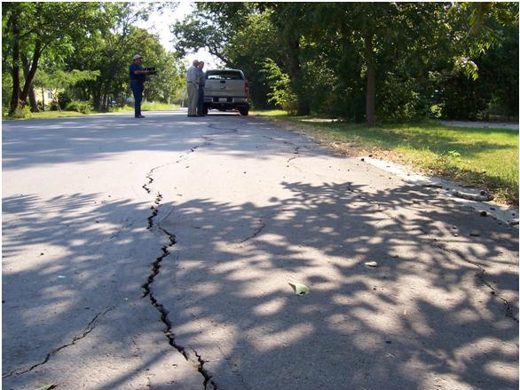
The City of Hutto reconstructed some of their downtown streets in 2005-2006. The design and construction ignored the geotechnical recommendations concerning subgrade improvement (due to cost), and the results were predictable (expansive clay cracking the streets), much to the chagrin of the complaining populace.
This is what happens when you place concrete pavement on expansive clay soil without proper detailing recommendations by a Geotechnical Engineer (or at least one who is experienced and understands how to handle this environment). This is not a joint, this is a large crack within the panel that is exhibiting both crack faulting and separation cracking.
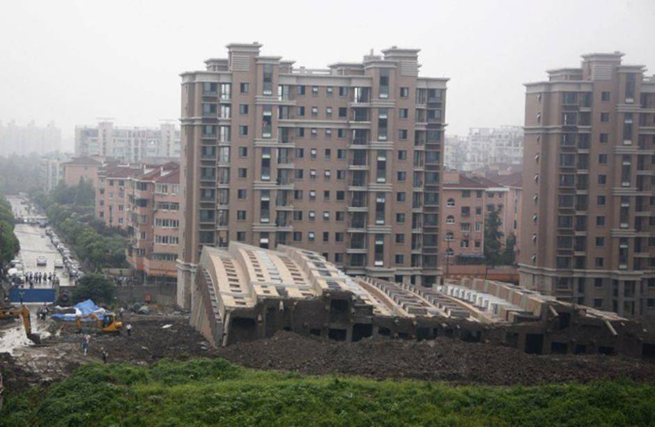
A bulging CMU basement wall can occur if the wall was not designed for the proper soil-related design parameters (retaining wall design) and drainage considerations.
This was a cheap single-block width screenwall at the Sunfield development in Buda, subsequently torn down because of failures, that was placed on expansive clay soil. Screen walls, retaining walls, pavement, must all be engineered (Structural Engineer, Geotechnical Engineer), otherwise you risk experiencing costly failures and replacement work.
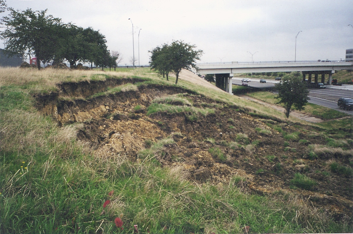
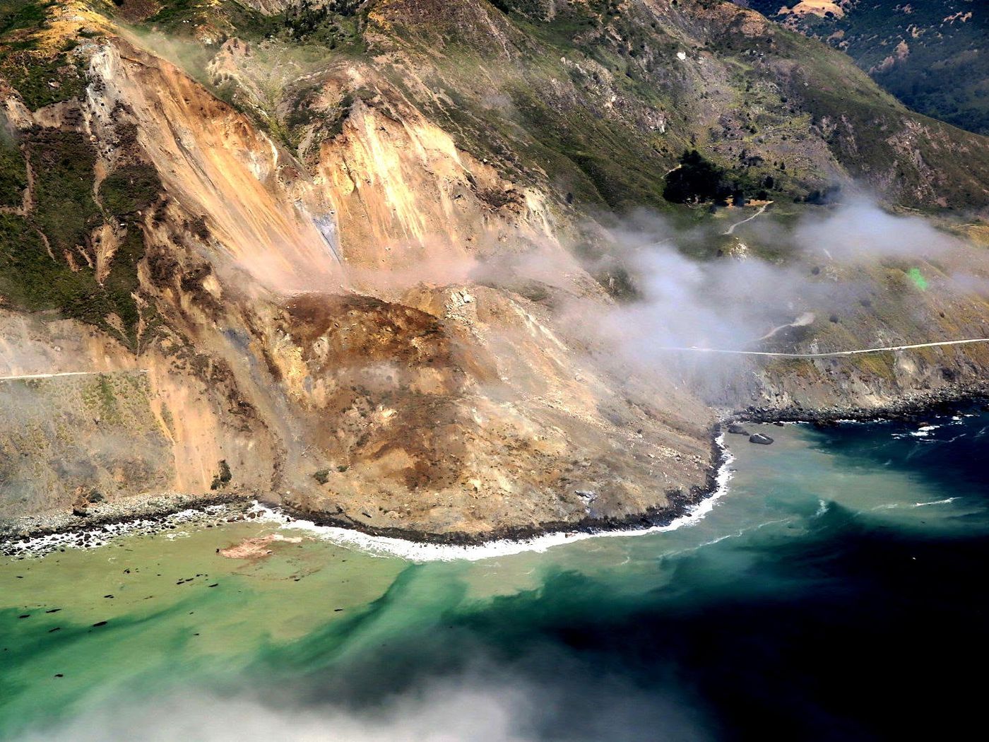
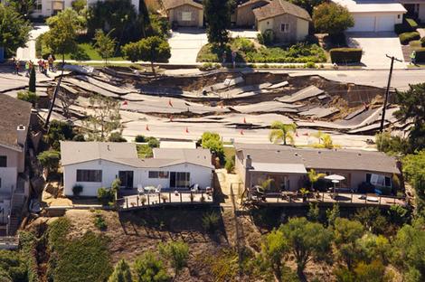
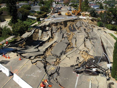
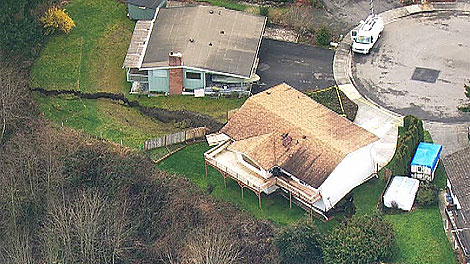
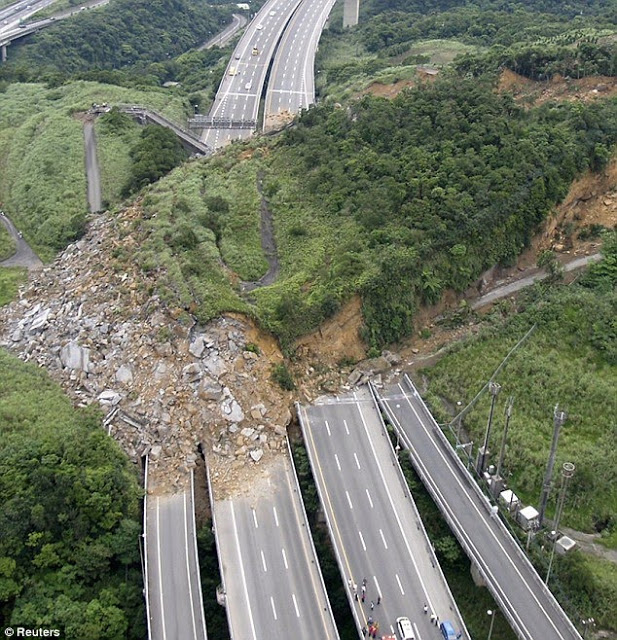
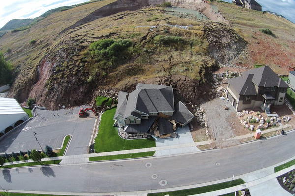
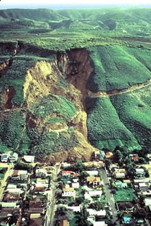
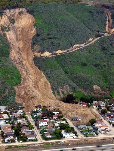
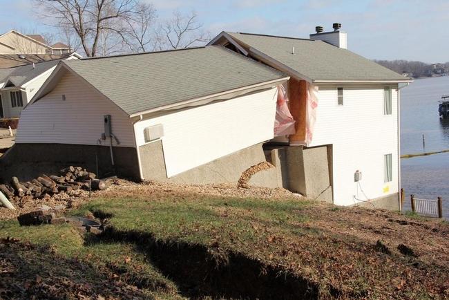
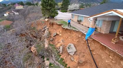
In 2019 west of Austin, Texas, a 200 ft long alignment of tall vertical limestone rock face collapsed. The site was a well known rock climbing face at Reimers Ranch Park off Hamilton Pool Road. The collapse finally occurred after rainfall had weakend fracture planes behind the bluff. Luckily the event occurred when no one was present.
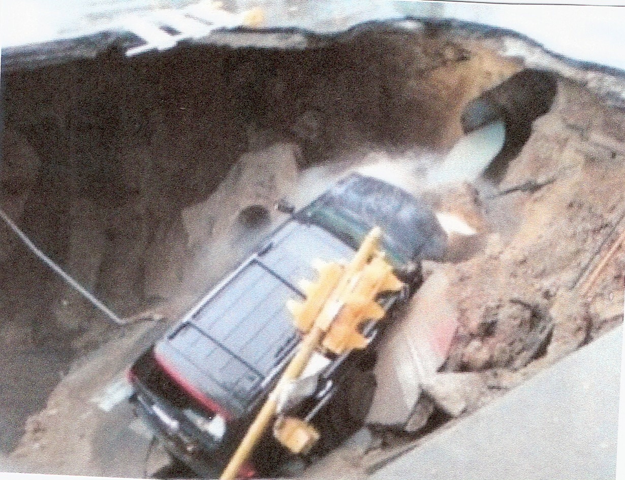
Photo credit: James Estrin. NY Times, 2005.
Photo credit: Hangry Fork, 2016

Note: the following section of this webpage is for educational purposes to serve the public by presenting examples of geotechnical engineering failures. These historical case histories do not adversise or promote any particular commercial services.
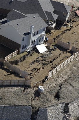
This was a part of the infamous retaining wall failure in San Antonio that damaged many homes that were above the wall system. Photograph credit: San Antonio Express News, Jerry Lara. Retaining wall failures are caused by any number of conditions such as:
- The design earth pressure was not reasonably estimated, or even worse the wall was not engineered and the as-built c
condition did not account for the proper earth pressure.
- The wall design did not account for hydrostatic water pressure (wall system not properly drained, or drainage system not maintained).
-The wall design did not account for sloping soil above or below the wall.
- The wall design did not account for swelling clay backfill behind the wall.
- The wall design did not account for settlement of the wall footing.
- The anchored wall (i.e. soil nails, pre-stressed anchors) did not have anchors adequately embedded.
- The wall design did not account for surcharge loads above and behind the wall.
- The wall design did not account for global slope stability (i.e. geotechnical analysis).


